Solenoid-Driven Metering Pumps PW
Brochures
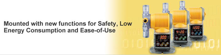
Features
Safety
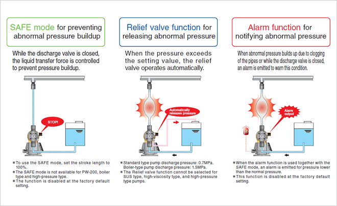
Three Types of Safety Features Offer Higher Level of Risk Control
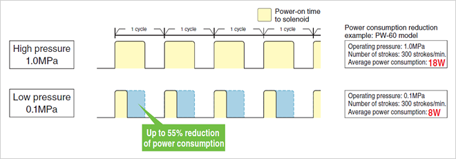
ECO mode
[1:10]
Energy-Saving Characteristics
In ECO mode, the running status is constantly monitored to automatically reduce electricity usage when running at low pressure.. Previous models supplied constant electricity regardless of discharge pressure.
Ease-of-Use
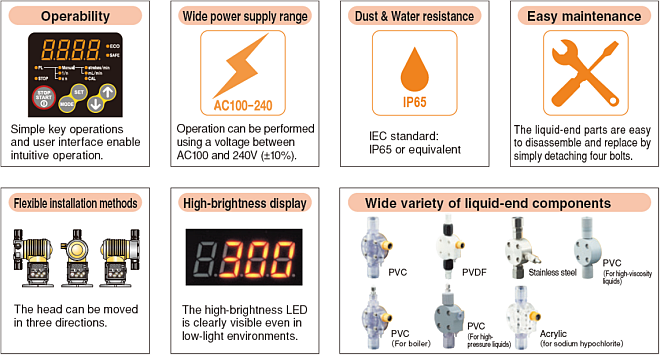
Functions Common to All Models
Manual Operation
- Stroke count control
- Can be set in units of a single stroke.
- Discharge amount control (PW only)
- Can be set in units of 0.1mL/min.
External Operation/Stop Control
The pump can be turned ON/OFF via external signal input.
Alarm Output
Use with a level measurement instrument and a discharge amount checker to generate an alarm when an abnormality occurs.
Synchronized Pulse Control
A single pulse can be generated for a single pump action. The generated pulse can be entered to a second pump for synchronized operation.
- Ex.) Control can be set so that in response to a single stroke at A, there are three strokes at B, two strokes at C, etc.
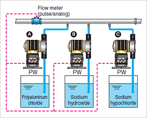
Signal Distribution
The connection below can be used without a signal distributor.
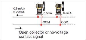
Pulse Signals
This unit can be connected in parallel to multiple pumps.
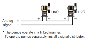
Analog Signal
This unit can be connected in parallel to multiple pumps.
Function of PW and PWT Only
- * PWT can be set only if timer function is in use
Pulse Input Proportional Control
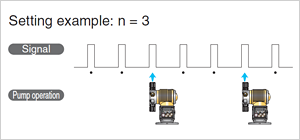
Pulse Frequency Dividing
The pump is operated one time per n times of input pulse.
- Setting range
- n=1~999

Pulse Magnitude
The pump is operated n times per each input pulse.
- Setting range
- n=1~999
Function of PWM Only
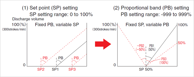
Analog Input Proportional Control
Automatic Operation
Receives an analog input signal (4 to 20 mA) and operates within the range of 0 to 300 strokes/min based on set values (target value and proportional band).
Function of PWT Only
Control of Timer Type
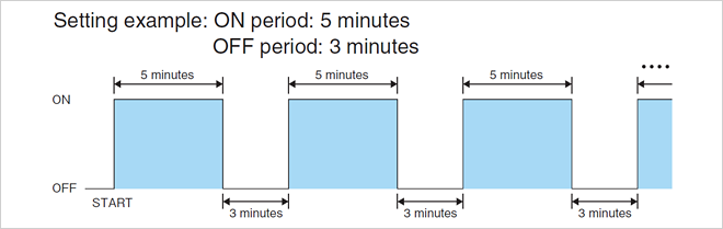
Interval Mode
Turns operation ON/OFF at a set interval.
ON time and OFF time can each be set to any single pattern in the range of 1 to 9999 minutes.
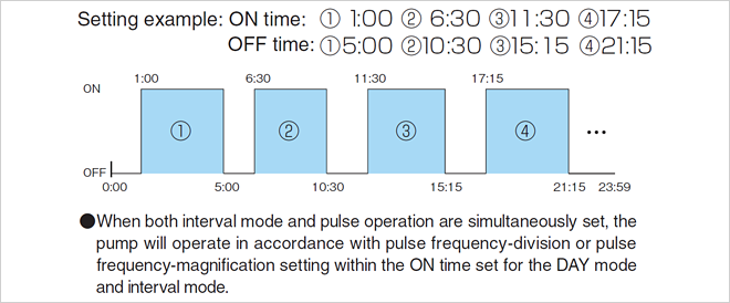
DAY Mode
Automatic operation starts every day at the same ON/OFF time set. Programs can be set in units of 1 minute within the range of 0:00 to 24:00 in a maximum of 9 patterns.
- * Cannot be used in conjunction with WEEK mode.
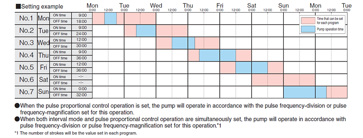
WEEK Mode
Automatic operation starts every week at the same ON/OFF time and day set.
The program can be set to one pattern per each day of the week, and the ON time to a time within the range of 0:00 to 24:00 and the OFF time to a time within the range of 0:00 to 48:00 in units of 1 minute.
- * Cannot be used in conjunction with DAY mode.
Specifications
For Injection of Generic Chemicals
| Model | PW・PWM・PWT | |||||||
|---|---|---|---|---|---|---|---|---|
| 30R | 60R | 100R | 30 | 60 | 100 | 200 | ||
| Max. discharge volume | (mL/min) | 30 | 60 | 100 | 30 | 60 | 100 | 220 |
| Max. discharge pressure | (MPa) | 0.7 | 1.0 | 0.7 | 0.2 | |||
For Injection of High Viscosity Medicines
| Model | PW・PWM・PWT | ||
|---|---|---|---|
| 60 | 100 | ||
| Max. discharge volume | (mL/min) | 60 | 100 |
| Max. discharge pressure | (MPa) | 1.0 | 0.7 |
For Injection of Boiler Chemicals/High-Pressure
| Model | PW・PWM・PWT | |||
|---|---|---|---|---|
| 30R | 30 | 30 | ||
| Max. discharge volume | (mL/min) | 28 | 25 | |
| Max. discharge pressure | (MPa) | 1.5 | 2.0 | |
For Injection of Sodium Hypochlorite (NaClO)
| Model | DCLPW・DCLPWM・DCLPWT | CLPW・CLPWM・CLPWT | |||||||||||
|---|---|---|---|---|---|---|---|---|---|---|---|---|---|
| 30R | 60R | 100R | 30 | 60 | 100 | 30R | 60R | 100R | 30 | 60 | 100 | ||
| Max. discharge volume | (mL/min) | 30 | 60 | 90 | 30 | 60 | 90 | 30 | 60 | 90 | 30 | 60 | 90 |
| Max. discharge pressure | (MPa) | 0.7 | 1.0 | 0.7 | 0.7 | 1.0 | 0.7 | ||||||