Basics|Precision pumping technology 9-3. Solutions for Gas Lock: Removing the Bubbles Inside the Pump Head
Removing the Bubbles Inside the Pump Head
Once a gas lock forms, it is not easily resolved. The procedure described in the previous section "9-2. Solution for Gas Lock: Increasing the Pressure Inside the Pump Head So That It Exceeds the Discharge Pressure"
may not be a viable option at some sites. In such cases, you can install an air release valve in the pump head to remove the bubbles by force.
This method is used with compact diaphragm pumps with a relatively small compression ratio. There are two ways to approach the prevention of gas locks; keeping gas from entering the pump or removing gas that has entered the pump.
There are three key points for preventing gas locks:
- a)
Prevent air intake from the suction-side hose.
A common cause of gas lock is dry-running--which happens when the pump keeps operating even after all of the liquid in the tank is exhausted.
In this state, the pump will inevitably suck in air, creating a high risk of gas lock.
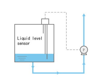
In this case, it is a good idea to design a system that involves a sensor that monitors the liquid level as shown in the figure to the right and a mechanism that triggers an alert and/or supplies liquid when the liquid level is low. - b)
Quickly discharge the bubbles that enter the pump head.
It is normal for a small amount of bubbles to enter the pump head intermittently or continuously, except for cases like a) above. With this in mind, the flow path in the pump head should be designed so that air can be quickly removed; in other words, the system should have a configuration that prevents the accumulation of air in the pump to the extent that it causes a gas lock.
However, as mentioned previously, shorter stroke length can relatively reduce the compression ratio. This causes bubbles to accumulate inside the pump head, which creates an environment where a gas lock can easily occur. - c)
When dealing with liquid that easily vaporizes, thoroughly examine the nature of the liquid and plan measures to prevent the generation of gas.
Sodium hypochlorite is an example of liquid that very easily turns into gas. When transferring such a liquid, you should thoroughly examine its properties and adopt the ideal conditions for liquid transfer so as to suppress the generation of gas as much as possible.
As we have reviewed above, air (gas) that entered the pump head can cause a gas lock.
A Gas Lock May Occur When the Liquid Level Drops in the Chemical Tank
Even when the amount of bubbles is such that does not result in a gas lock, it cannot go ignored. This is because small bubbles can expand when the liquid level drops in the chemical tank, resulting in a gas lock.
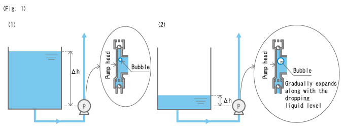
When the liquid level in the tank is high, as shown in Fig. 1 (1), the bubbles inside the pump head are compressed and small due to the weight (pressure) of the liquid. However, when the liquid level in the tank drops, as shown in Fig. 1 (2), the pressure applied by the liquid gets smaller, and the bubbles inside the pump head expand. In this state, bubbles inside the pump head may expand to a size that can cause a gas lock.
To put it simply, when the tank is filled with liquid, a gas lock may not occur even when bubbles have entered the pump head; however, when the liquid level drops, bubbles can expand to a size that can cause a gas lock.
To make matters worse, bubbles inside the pump head can also affect the pump's discharge volume.
In conclusion, the inclusion of bubbles inside the pump head can affect the discharge volume with the changes in the liquid level in the tank. Specifically, the discharge volume decreases when the liquid level drops.
The relationship between bubbles and the discharge volume is shown below. (Fig. 2)
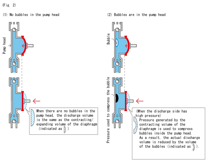
- Notes
- The phenomenon as shown in Fig. 2 (2) only occurs when the discharge side is under high pressure. However, some loss of discharge volume that occurs with the compression of bubbles cannot be avoided even at lower pressures, although the degree of impact is less significant.
Expanding on this basic understanding, the larger the bubbles inside the pump head become, the more portion of the contracting/expanding volume used to compress these bubbles increases, which leads to reduced discharge volume. This can further lead to a gas lock.
It was mentioned previously that a drop in the liquid level in the chemical tank increases the size of the bubbles in the pump head. This means that the discharge volume decreases along with the lowering of the liquid level in the tank.
As a rule, diaphragm pumps are not supposed to have fluctuations in discharge volume due to changes in the liquid level in the suction-side tank. However, when bubbles enter the pump head, such fluctuations in discharge volume can actually happen.
The key points of gas locks are summarized below:
- (1)
Higher pressures on the discharge side make gas locks more likely.
- (2)
Gas locks are less likely to occur in large-capacity pumps (several hundred mL/min. or larger).
- (3)
Small-capacity pumps (particularly, several dozen mL/min. or smaller) are more prone to gas locks compared to larger pumps.
- (4)
Shorter stroke lengths make gas locks more likely.
- (5)
Gas locks tend to occur when a large amount of bubbles enters the pump head at once.
- (6)
Gas locks are less likely to occur when bubbles only enter the pump head in small amounts.
Gas locks are also discussed in the Topic "What is Gas Lock?" A video on TACMINA's anti-gas lock pump, designed specifically for the sodium hypochlorite process, is also available for your viewing ("Actual video of automatic air release mechanism").
TACMINA's DCLPW Series, dedicated to sodium hypochlorite injection, offers a perfect solution to injection problems with its double block mechanism that prevents gas locks.
More...
Articles List for Precision pumping technology
- 9-4. Gas Lock Caused by Rapid Liquid Temperature Change
- 9-3. Solutions for Gas Lock: Removing the Bubbles Inside the Pump Head
- 9-2. Solution for Gas Lock: Increasing the Pressure Inside the Pump Head So That It Exceeds the Discharge Pressure