

Basics|Precision pumping technology 7-3. Preventing Cavitation
Preventing Cavitation
Basically, you only need to consider the opposite of the factors that facilitate cavitation, namely:
- a)
Shorter suction-side piping
- b)
Larger pipe diameter
- c)
Slower stroke speed
- d)
Improved pump suction conditions → Use a configuration with the pump situated lower than the tank whenever possible
Also, as mentioned in the section about inertial resistance ("3-2. Solutions to Overfeeding 1: Reducing the Inertial Resistance"), the most practical and effective solution is to use a larger pipe diameter (b). This is because the value of inertial resistance is inversely proportional to the square of the inner diameter of the pipe.
Here, let's focus on d) improving the suction conditions for the pump. Cavitation occurs due to a pressure drop inside the pump or the suction-side piping. That means that cavitation will not occur as long as a pressure greater than the pressure drop is applied to the suction side. For example, if a pressure drop of -0.02 MPa occurred inside the pump, you only need to apply a pressure greater than 0.02 MPa to the suction side. In practical applications, the tank has a sealed structure, and is pressurized with nitrogen gas.
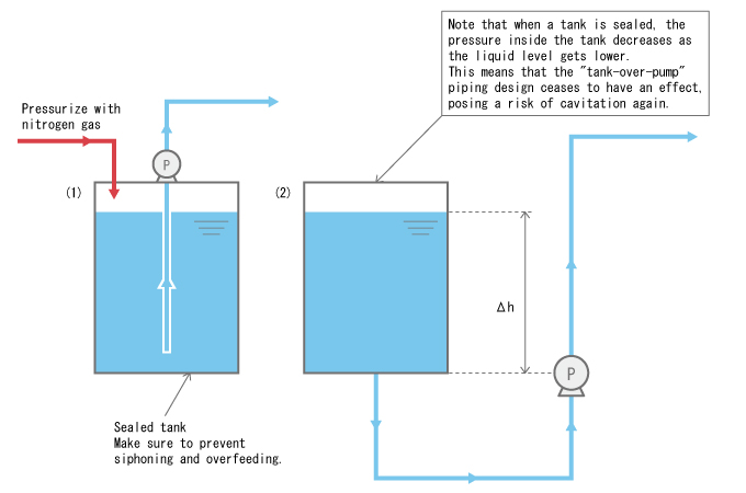
However, this method has a few problems: first, implementing a sealed structure for the tank can be costly, and secondly, excessive pressurization can create a risk of the tank bursting. Careful consideration is needed for the design.
"Tank-Over-Pump" Configuration
So, let's think of a way to pressurize the pump's suction side without using a sealed tank.
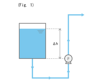
When the tank is placed as shown in Fig. 1, the weight of (pressure from) the liquid from the liquid surface in the tank to the pump is applied to the suction side of the pump, supplementing the pressure drop from inertial resistance. This is the press-in condition in a "tank-over-pump" configuration.
For example, if the liquid is water, a press-in pressure of 0.01 MPa (water head) can be obtained for each meter of water height.
Precautions for Creating a Press-In Condition
- (1)
As mentioned at the beginning of this lecture series, piping as shown in Fig. 1 is prone to siphoning and overfeeding. Careful consideration is needed for the planning of the injection point.
(e.g. installation of an anti-siphon check valve or back pressure valve) - (2)
When implementing a press-in piping design, you must review the overall effect also considering the piping length.
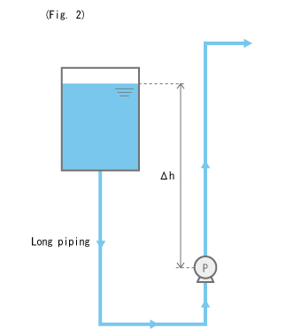
When adopting a press-in piping design like that illustrated in Fig. 2, make sure that the suction-side piping is not too long.
Longer piping means increased resistance in the piping.
(While you can use a thicker pipe, not only would it cost more, it increases hassles related to maintenance.)
The Triple Smoothflow Pump Configuration Is Preferable for Metered Transfer of Volatile Liquids
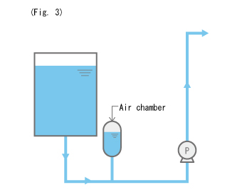
You have already learned that placing an air chamber in the discharge-side piping can reduce inertial resistance. Of course, it is theoretically possible to install an air chamber on the suction side, and there are real-life examples (Fig. 3).
However, this not only makes the piping complex, but also causes a maintenance problem: supplying air becomes difficult (too much air makes the air inside the air chamber enter the pump).
In this sense, the use of an air chamber on the suction side is not very practical, unless maintenance staff is on duty at all times.
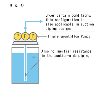
A triple Smoothflow Pump configuration achieves non-pulsation on both the discharge and suction sides, contrary to the dual Smoothflow Pump configuration that produces pulsation on the suction side. (However, the pulsation rate in the suction-side piping is, theoretically speaking, better with the dual Smoothflow Pump configuration.) Using the triple serial Smoothflow Pumps can eliminate pulsation, which as a result suppresses inertial resistance, making cavitation very unlikely to occur. (Fig. 4)
While inertial resistance is not present in continuous flow, even when there is no pulsation the frictional resistance that occurs between the liquid and the inner walls of the piping still remains.
The triple Smoothflow Pump configuration is also suitable for the following applications in addition to metered transfer of volatile liquids.
- (1)
Non-pulsating metered transfer of highly viscous liquid.
- (2)
Transfer of settling slurry (liquid containing granular substances). If a pulsating pump is used, the slurry will settle when the pump is in its suction cycle, that is, when the pump is not discharging--this may lead to cases where only the liquid part enters the pump head. In contrast, liquid flows continuously in the piping of a configuration using triple Smoothflow Pumps. This leaves no time or space for the slurry to settle, enabling the stable transfer of the slurry.
- *
However, the flow velocity inside the piping must be greater than the settling speed of the slurry. Taking this into account, the triple Smoothflow Pump configuration is still desirable as it can increase the flow rate by using a narrower pipe, thanks to the non-pulsation feature on the suction side.
- *
The particle size of slurry that can be transferred using a diaphragm pump is--although it also depends on the properties of the slurry--about 100 μm, with a weight concentration of around 10%. (Customized models are available according to the slurry properties. Contact TACMINA for details.)
Weight concentration: Weight of slurry / (Weight of slurry + Weight of liquid) x 100